
I have been woefully absent from these pages the last several months since we started the design effort on the new engine. I am excited to finally be able to share what the team has been working on so dilligently. The MkII Clarke-Brayton Engine is the next step in dramatically reducing fuel consumption in trucks, automobiles and generators without increasing costs. It is also the next step in developing a highly efficient compression-ignition 100% natural gas engine that can meet the up-coming greenhouse gas emissions regulations. This is a boxer configuration split-cycle engine implementing what we have come to call the Clarke-Brayton cycle. The thermodynamics of this engine are virtually identical to our previous “CCI” design but are implemented in a much more conventional way. Everything that we published in our SAE paper at the 2013 World Congress holds true for this engine, but many of the difficulties related to the old engine are resolved.
MkII Clarke-Brayton Engine

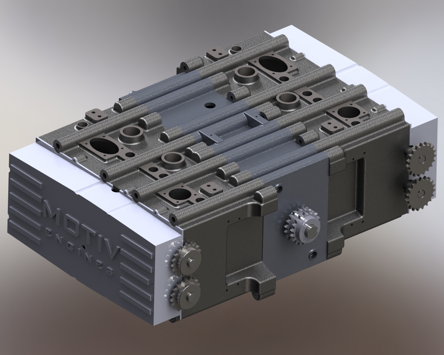
Section of the MkII engine
As with the previous design, in the MkII air moves sequentially through three cylinders, starting at the mid-sized cylinders at the top of the section image. This architecture allows us to achieve a 56:1 compression ratio leading to a 30MPa peak pressure. It has far less surface area for heat loss than a comparable conventional diesel due to the very small bore of the combustion chamber. The small combustion piston area leads to lower forces on the crank than a conventional engine would have if it were able to reach similar pressures, reducing rod bearing friction compared to conventional architectures. A lack of net forces on the main bearings due to the opposing forces of the piston pairs reduces main bearing friction compared to conventional engines. It expands exhaust gasses all the way to ambient pressure before the exhaust stroke. Gas transfer from one cylinder to the next is begun at equal pressures on either side of the valve, which keeps velocities low, minimizing pumping losses and eliminates blow-down. The power is produced in almost a 50-50 split between the combustion (central) and exhaust (largest) pistons. There is a power stroke every revolution. All valves are actuated by overhead cams. Piston ring sealing is completely conventional, eliminating the dynamic effects of the old design and greatly reducing the reciprocating mass.
The major components of the MkII Clarke-Brayton Engine have already been released to the foundry for casting and everything else should be released for fabrication within a couple of weeks. We will test this summer at a globally renowned engine development lab and I hope to have results to share shortly after that.
A team of just three people designed the MkII from a back-of-the-napkin idea to a fully developed test engine in 7 months. Azra Horowitz and John Clarke have both put in herculean efforts to get this done in time despite a couple unexpected thorny technical challenges along the way. I could not be more proud to be working with them.

Thank you for your effort on the development.
How much is the power in HP of your engine developed.
Also the power/weight, size and etc for the prototype.
whta is your developnig schedule for commercial engine.
Regards
Hoon Heo
Hi Hoon – at 2200 rpm this engine should produce 146 horsepower. We do not plan on running it any faster than this, but the eventual commercial engine we hope to have a rated speed at around 3600 rpm for an engine of this size. This prototype was not designed to be light – It was overdesigned in an abundance of caution in many places, and also to make the monoblock (head plus block cast as a single piece) to be identical on both sides of the engine to reduce costs.
Dear Ed O’Malley
I heard about your work from Glenna, sister of Prof. Stearman at UT Astin who supervised me while I was studying in U.S. last 1979~81.
I am very happy to see you are doing a great job.
Let me ask questions as follows
(1)As far as diesel engine is concern, what is your solution to replace “CRDI” technique? Have you developed any alternatives or what ?
(2) what is the dimension of the engine a’ssy?
(3)Also what is your schedule of R&D or development?
I am going to visit U.S from 1st through 11th of this July.
Might there be any chances for me to visit your place and see your work?
This engine will not be installed on sports cars, motorcycles or airplanes because big, heavy and slow.
Until you can put it in a pick-up truck, it’s just another pipe dream like Ecomotors or Pinnacle. These are all great engines but putting them into production to meet the needs of the OTR industry is still decades away. This doesn’t even take into account the economics of large companies, Cummins, Navistar, of producing cheaper engines to undercut the new technology.
I’m not in your industry, but am involved in the development of complex technology that has taken years and nearly $400M of seed money from private equity. Kudos to you for sticking to this and thinking carefully about the many variables required to generate this concept, make molds, and do the casting + testing. I trust you do well and can eventually commercialize this concept.
Thanks Marc! Glad to hear from someone else doing challenging technological development. I’m feeling confident about our chances.
I really enjoy the article post. Cool. fffdacbdcdec
Beyond glossy CAD renderings, at least one of your site’s images appears to show a test-bed photo. Numerous commercial diesel applications require so many duty-cycle hours per year that annual fuel costs greatly exceed engine purchase prices depreciated over their service life years. So the primary question after EPA-emissions compliance and durability issues is Brake Specific Fuel Consumption. So what was the lowest (best) BSFC value any of your test engines produced anywhere on its BSFC map? Any new design that can’t improve on VW-Audi’s TDI diesel BSFC values can’t be expected to capture market share. We can convert between any measurement units you prefer. Please tell your interested tracking parties what your engine’s lowest BSFC test result was.
LoveLearn
Hi LoveLearn – You are right – a large improvement in BSFC over the current state-of-the-art is required for successful commercialization of an alternative architecture engine. Our first generation prototype did not generate the BSFC needed. This was due to some leakage caused by dynamics that are quite different in that concept from a conventional engine. However it was able to confirm that our thermodynamic simulation on which we base our BSFC potential is correct. When we included the leakage experienced on the first prototype, the engine results matched the simulation. Therefore we re-designed the engine to address all the shortcomings we identified with the first prototype and now we are building the second one. I am optimistic that BSFC results will be very promising with the second design. Thanks for your interest!
Team congratulations on your great achievement, well done. Petrol Head and the Thruflow Valve Designs Team are eager to introduce our valve concepts. Our design fits any machine as it eliminates valves and camshafts entirely. We note that you still make use of these.
I’m pleased that your group is continuing its engine development progress toward
creating a compelling replacement for conventional evolved and tweaked roughly
hundred-year old configurations. You claimed that lowering crankshaft bearing
loadings, which to my mind necessarily includes both connecting rod bearings and
main bearings, would significantly lower friction. We’ve chased that pipe dream
but learned that so long as those bearings are hydroscopically supported (full
fluid film support), reducing loading pressure does NOT significantly lower friction.
Published comparable bearing load/friction curves will verify this.
You also mentioned decompressing combustion gasses all the way down to ambient
pressure. If you do that, need for a muffler will nearly disappear. Conventional
engines’ exhaust racket is principally caused by intermittently releasing much-higher
than ambient blasts. I’m sure you meant that your design decompresses to a
pressure much closer to ambient and some pressure differential is required to
force flow.
Decompressing post-combustion gasses to approach ambient pressure will obviously
capture energy as crankshaft-spinning force which conventional engines can’t
capture. That more-complete decompression will lower exhaust temperatures.
As combustion gases are decompressed, various throttle positions and loadings
predict a complex map of dew points where saturated-gas condensations begin.
Acidic condensation within the exhaust system require selecting appropriate
stainless steel containment to avoid short service life. You should keep
decompressed combustion products hotter than dew-point onset while inside
your final decompressing cylinder. Hitting the dew point causes instant pressure
collapse (terminating piston pushing) while acidic mist attacks rings and cylinder
walls.
Other than the friction savings you hoped to obtain, I expect you have already
considered these other issues. Congratulations on your progress and keep up the
good work.